

Key Takeaways
- Standardized Signals: DB9 connectors primarily support serial communications like RS-232, while DB25 supports both multi-channel serial setups and legacy parallel printer interfaces.
- Electrical Limits: Standard D-Sub contacts handle current ratings of 3A to 5A per pin with contact resistance under 10mΩ and operating temperature ranges from -55°C to +105°C.
- Shielding Performance: Metal and metallized plastic backshells offer 40dB to 60dB of EMI/RFI attenuation across frequencies from 30MHz to 1GHz.
- Custom Wire Harnesses: Selecting pre-molded or custom-assembled housings ensures structural stress relief and reliable performance in high-vibration industrial environments.
What is a D-Sub Connector and How Does It Work?
A D-Subminiature (D-Sub) connector is an electrical connector featuring a distinctive D-shaped metal shield that provides structural support, ensures correct orientation, and guards against electromagnetic interference. D-Sub connectors consist of two or more rows of contacts enclosed in a protective shell, available in plug (male) and socket (female) configurations. They maintain a critical role in industrial automation, legacy computing, and commercial equipment due to their mechanical durability, low contact resistance, and secure screw-locking mechanisms.
What Are the Key Differences Between DB9 and DB25 Connectors?
While both options share similar mechanical characteristics, their physical layout, signal capacity, and primary application domains differ significantly.
- Physical Dimensions: DB9 shells feature 9 contacts arranged across two rows (5 top, 4 bottom). DB25 shells house 25 contacts across two rows (13 top, 12 bottom).
- Application Scope: DB9 serves primarily as the physical interface for serial protocol buses like RS-232, RS-422, and RS-485. DB25 supports complex multi-signal configurations, including IEEE 1284 parallel interfaces, multi-channel serial devices, and audio snake systems.
- Electrical Parameters: Standard contacts maintain contact ratings between 3A and 5A, dielectrics withstand 1000V AC RMS for 1 minute, and insulation resistance exceeds 5000MΩ at 500V DC.
| Feature / Specification | DB9 Connector | DB25 Connector |
| Pin Count / Arrangement | 9 pins (Rows: 5, 4) | 25 pins (Rows: 13, 12) |
| Shell Size Code | DE-9 (Standard size E) | DB-25 (Standard size B) |
| Primary Interfaces | RS-232, CAN bus, RS-485 | Parallel port, IEEE 1284, Audio |
| Current Rating (Per Pin) | 3A to 5A continuously | 3A to 5A continuously |
| Maximum Voltage | 300V AC/DC RMS | 300V AC/DC RMS |
| Typical Cable Gauge | 22 AWG to 28 AWG | 22 AWG to 28 AWG |
How to Wire Standard DB9 Pinouts for RS-232 Serial Communication?
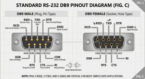
Wiring a DB9 pinout for serial interfaces requires mapping line assignments correctly to maintain full-duplex communication and hardware handshaking.
- Analyze the standard RS-232 assignment scheme: Pin 2 (Receive Data / RXD), Pin 3 (Transmit Data / TXD), and Pin 5 (Signal Ground / GND).
- Verify control lines: Pin 1 (Data Carrier Detect / DCD), Pin 4 (Data Terminal Ready / DTR), Pin 6 (Data Set Ready / DSR), Pin 7 (Request to Send / RTS), Pin 8 (Clear to Send / CTS), and Pin 9 (Ring Indicator / RI).
- Select between straight-through or null-modem cabling. Straight-through cables connect matching pin numbers directly for DTE-to-DCE setups. Null-modem configurations swap RXD/TXD (Pins 2 and 3) and cross-connect RTS/CTS (Pins 7 and 8) for direct computer-to-computer connections.
- Inspect solder joints or crimp connections to ensure contact resistance remains below 10mΩ.
How to Wire DB25 Pinouts for RS-232 and Parallel Interfaces?
The DB25 pinout serves dual roles depending on whether you configure it for RS-232 serial or IEEE 1284 parallel operations.
- Map RS-232 serial lines: Pin 2 (TXD), Pin 3 (RXD), Pin 4 (RTS), Pin 5 (CTS), Pin 6 (DSR), Pin 7 (Signal Ground), Pin 8 (DCD), and Pin 20 (DTR).
- Configure IEEE 1284 parallel pinouts: Pin 1 (Strobe), Pins 2-9 (Data Bits 0-7), Pin 10 (Acknowledge), Pin 11 (Busy), Pin 12 (Paper Out), Pin 13 (Select), and Pins 18-25 (Ground Return Paths).
- Measure loop resistance across ground lines to confirm ground loops do not induce noise levels higher than 50mV peak-to-peak on critical data channels.
How Do You Select the Right Backshell Housing for Your Assembly?
Selecting an appropriate hood or backshell protects fragile wire terminations, maintains strain relief, and prevents stray noise from entering signal lines.
- Evaluate environmental shielding needs. Metal (zinc die-cast) and metallized plastic housings provide 40dB to 60dB of shield effectiveness across frequencies from 30MHz to 1GHz. Plastic housings suit light-duty, cost-sensitive, non-shielded applications.
- Determine cable exit directions. Choose 180-degree straight exit hoods for direct inline cabling, 90-degree right-angle hoods for tight spatial enclosures, or 45-degree angled entry housings for dense rack arrangements.
- Verify strain relief mechanism compatibility. Ensure internal clamping screws or rubber grommets clamp the outer cable jacket firmly, resisting tensile pull forces up to 150N.
Frequently Asked Questions
1.What is the difference between a DB9 connector and an DE-9 connector?
“DB9” is the widely used common term, but “DE-9” is the technically accurate original designation. The “D” stands for the D-Sub series, “E” specifies the smallest shell size, and “9” denotes the pin count.
2.What is the maximum cable length for RS-232 DB9 communication?
At standard baud rates of 19,200 bps, unshielded RS-232 cable lengths should not exceed 15 meters (50 feet). Using low-capacitance shielded cables from LCSC Cable allows longer cable runs up to 100 meters at reduced transmission speeds like 4,800 bps.
3.Can I adapt a DB25 port to a DB9 port directly?
Yes, using a passive pin adapter or custom cable assembly. Because both formats use the same underlying RS-232 voltage signaling scheme, signal wires simply map directly between corresponding pins without requiring active protocol converters.
4.How do gold pin plating thicknesses affect connector lifetime?
Gold plating shields copper contacts from oxidation and corrosion. Gold flash (1-3µin) withstands up to 50 mating cycles, making it ideal for stationary connections. Heavy gold plating (15-30µin) supports over 500 mating cycles in high-wear application environments.
5.Why does my D-Sub connection require screw-lock hardware?
Jack screws (typically 4-40 UNC threads) mechanically fasten plug and socket shells together. This prevents accidental disconnections caused by mechanical vibration, cable strain, or accidental pulling in industrial control systems.
Conclusion: Final Verdict
Building robust, reliable interconnect systems relies on matching the right pin configurations, housings, and shielding techniques to your operational demands. For standard 9-line serial communications, DB9 provides a compact and economical footprint. For complex parallel or multi-signal wiring, DB25 delivers the expanded contact capacity necessary for stable performance. Pair your connectors with metallized or die-cast backshells to eliminate signal degradation from EMI.
Find What You Need on LCSC Cable
We support custom cable development including prototype sampling, covering consumer electronics, industrial systems and specialty applications. You can explore LCSC Cable’s extensive online catalog to find fully certified cables that match your design requirements, helping you build systems that deliver stable performance for years to come.